Flow-Simulations
of all 4 elements
... and their combinations
Flow-Simulations
of all 4 elements
... and their combinations
We specialize in reconstructing three-dimensional flows at customizable levels of fidelity to meet your specific needs. Leveraging advanced simulation technology, we design innovative products, rigorously test functionality, and gain deep insights into complex internal processes. With access to a wide network of specialists, we serve a diverse range of industries and cover a broad spectrum of physical phenomena. Our expertise in liquid/gas flow, thermal analysis, and combustion simulations enables us to provide comprehensive solutions tailored to drive innovation and efficiency in your operations.
Our elements


All kinds of combustion, chemical reactors, …

All gases at sub-, or supercritical condition


All kinds of (non-) newtonian liquids


Flow and settling of microparticles, like plastics or soot. Heat transfer in solid structures.
Example: High pressure steam generation by H2-O2-Combustion
There are multiple applications for high pressure steam generation in the industry. Among others it is used in the oil recovery process, paper production, space propulsion, ….
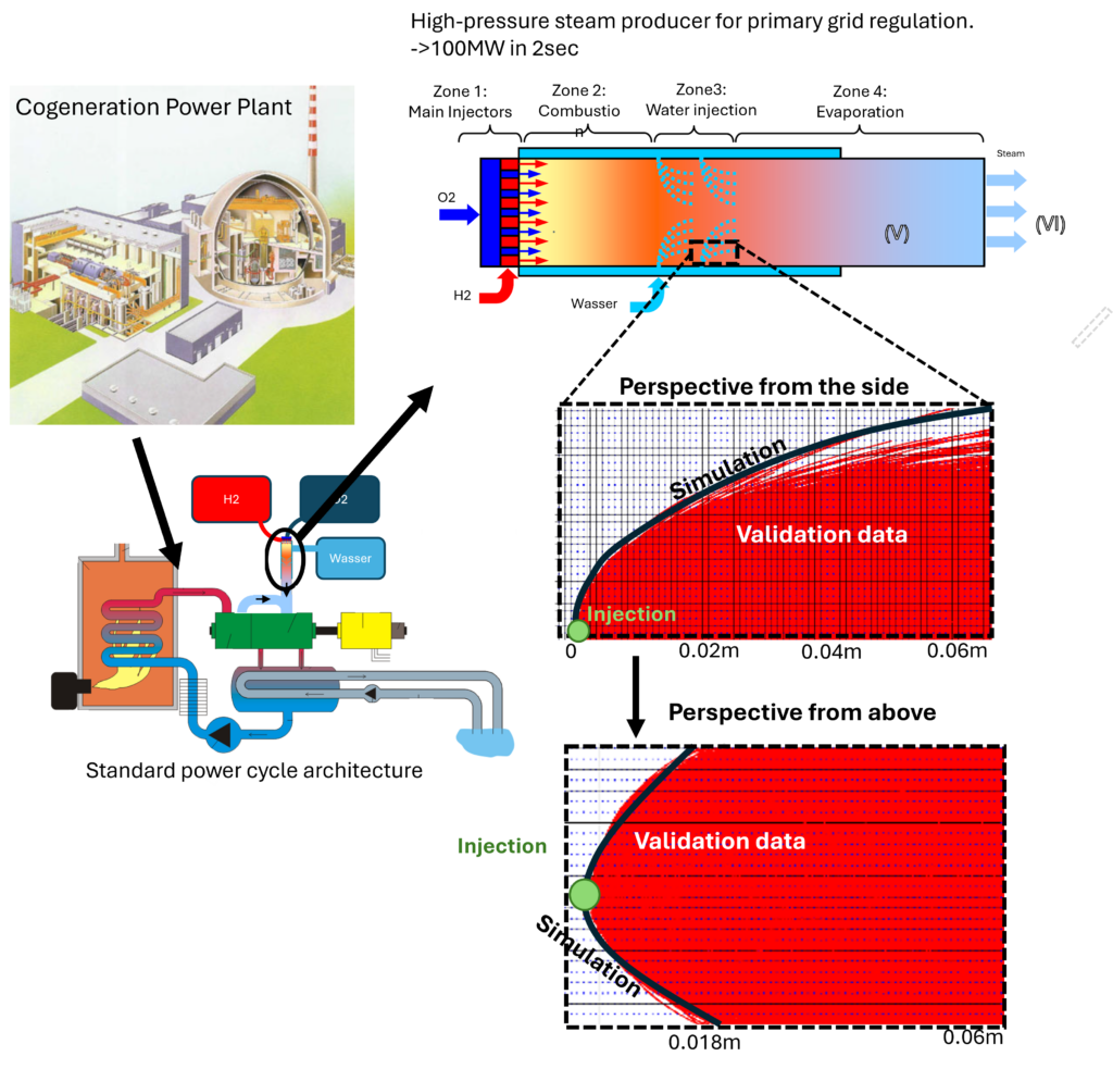
Here, we present our simulation and validation of a hydrogen-oxygen combustion chamber providing steam to the turbines in a power plant.
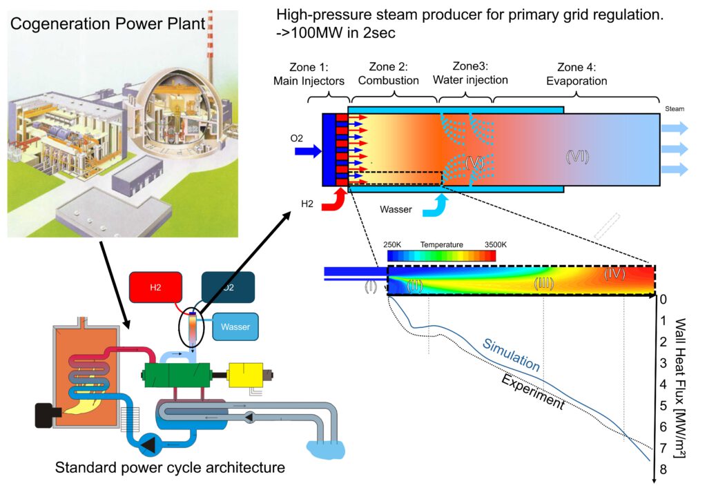
Processes inside the H2-O2 combustion chamber: Reactants are injected through injection tubes (I). They can have different shapes but in this case they are coaxial. Insite the chamber the reactants are ignited in many possible ways. A very common method of stabilization of the combustion process is a small hot recirculation region between the reactants (II). From the ignition region a reacting shear layer emerges in the shape of a fire tail. There, the advancing mixing combustion process expands the gas across the whole chamber (III). The result is a hot set of products in the state of chemical equilibrium at temperatures of around 3500K (IV). After an equilibrium temperature is reached, water is injected from the walls slowly cooling down the hot gas and moving its equilibrium state closer to the products.
Challenges and solutions:
a) Since the measurement inside combustion chambers is very challenging the available validation data is very scarce. However, in our network we have access to specialists, who could design experiments with reliable and reproduceable measurement data. Additionally, we established a technical unit which is conducting DNS simulations, which are basically virtual experiments. They provide deeper insights into the physical field in the combustion chamber.
b) The only affordable simulation methods for such an application are RANS and LES. In any case, the necessary level of abstraction and modelling is very high. In order to ensure that the applied models cover all relevant phenomena in these very special physical conditions adjustments have be made. The turbulence transport model has been enhanced to account for the combustion induced turbulence. The TCI-Model has been adjusted to the low turbulent Karlovitz numbers. Different models for thermophoresis as well as molecular energy transport has been tuned.
Relevant publications
Example: Heat transfer in rocket engine walls
Cooling channels are applied in different forms throughout different industries. Wherever high temperatures are endangering the structural integrity a fast evacuation of energy needs to be ensured.
High-perfomace cooling channels can locally create strong temperature gradients up to 500K/mm. That way, even the energies released in a rocket engine can be handled. This class of configuration has been simulated and compared with experimental measurements.
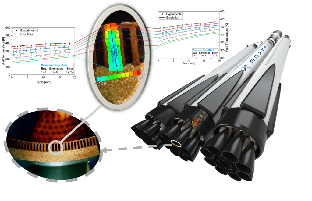
The test campaign, conducted as part of the Electrical Heated Curved Cooling Channel [EH3C] Project, is a validation case for the present numerical simulation. A straight cooling channel (made of copper) with a high aspect ratio of 0.5 × 4.6 × 300 mm was used. Thermocouples were attached to the channel walls to investigate the temperature distribution in the copper channel’s length and height. The figure shows the arrangement of the thermocouples on the EH3C test specimen, which extends along its entire length. The channel is divided into 14 sections along its depth, and each section has seven measuring points located at different heights. In order to predict the temperatures in the copper structure of the cooling channel, the exact thermal conductivity (λ) had to be determined. It is not a static value but strongly depends on the local temperature. A function λ(T) has been fitted to the heat transfer characteristic of the copper in the given case.
λ = 202.6011 + 1.3787 T − 1.1504 × 10⁻² T2 +
6.7138 × 10⁻⁵ T3 − 2.0282 × 10⁻⁷ T4 +
2.9330 × 10⁻¹⁰ T5 − 1.6264 × 10⁻¹³ T6
Another criteria for the heat transfer prediction is the correct capturing of the effects on the fluid-solid interface. There the thermal diffusivity is defined by the flow patterns of the cooling material. Therefore, the performance of the k − ω SST turbulence model is compared with experimental data on temperature and pressure drop. It was found that the k − ω SST model predicts the pressure drop well. In addition, there is a strong agreement between the simulated temperatures of the upper temperature sensors. However, the lower temperatures show an increasing deviation. The reason for that is pre-existing thermal stratification at the channel entrance, as the experimental setup does not have ideally thermally isolated channels.
Relevant publications
Example : Supercritical pseudoboiling LNG regasification plants
When gases surpass a characteristic pressure threshold, their thermophysical and transport properties are changing in a strongly non-linear way. They no longer obeys the ideal gas law. In addition, small hydrocarbon impurities have a significant effect on the fluid properties. Hence, complex real-gas equations are applied to model the fluid behavior under different operating conditions.
Ideal gas law: p=ρRT
Critical pressures: Oxygen (ca. 50bar), Hydrogen (ca. 13bar), Methane (ca. 46 bar), Nitrogen (ca. 33.5 bar)
There are different applications, which require the knowledge of the supercritical properties of gases. Two examples are the processes in regasification facilities and in the cooling channels of rocket engines. In both cases, liquefied natural gas (LNG) is being transformed back in its gaseous state by exposing it to high temperatures.
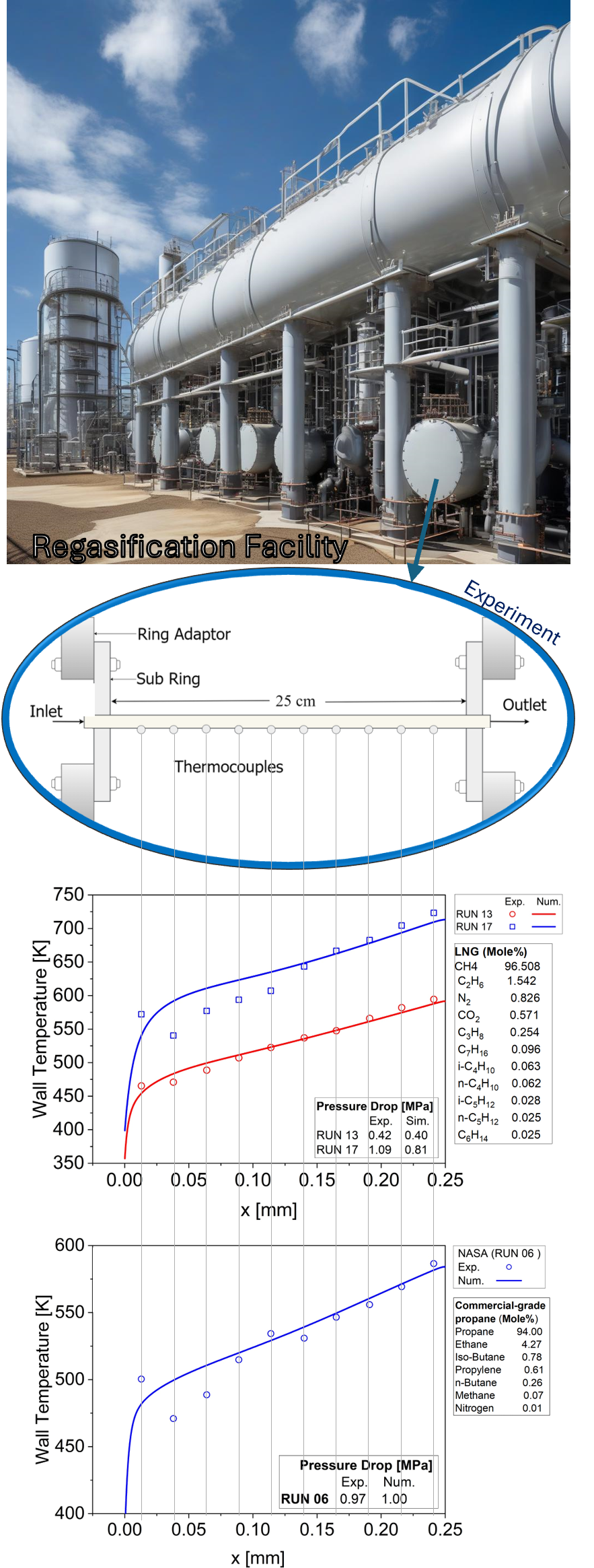
In this project, we investigate the effects of hydrocarbon impurities in LNG. Hydrocarbon impurities can lead to undesirable phenomena such as pseudo-boiling and two-phase flow, which affect the ability of the flow to exchange energy with the surrounding. By implementing complex real-gas fluid properties into a CFD setup, we could simulate the whole regasification process and predict local temperatures and pressures. This method allows an efficient development and improvement of such systems.
In order to conduct high-quality validation, experimental data from NASA was used. This data focuses on using LNG as a coolant in a heated tube under supercritical conditions. This study investigated heat transfer with LNG in an electrically heated round tube. The composition of the liquefied gas was 96.5 mol% methane for the first validation and 94.0-mole % propane for the second test. The comparison between the numerical model, including the GERG-2008 equation of state and ECS model, and the NASA experimental results show a very good agreement of wall temperature and pressure drop.
Relevant publications
Example : Liquid jet in crossflow
Optimization of steam generation through precise humidification is a very sensitive process which increases the safety and lifespan of the water cycles in the power plant.
Our simulation of a hydrogen-oxygen combustion chamber can be used to exactly regulate the steam supply to turbines in a power plant. We show that the strategic addition of cold water lowers the temperature of the hot products from 3500 K to around 1000 K, while reducing the concentration of non-condensable contents .
This particular case was performed to improve the accuracy of the Lagrangian method. The validation process involves comparing the simulation results data of higher fidelity.
This study shows a close agreement in terms of particle distribution. This project revealed the exact nature of the reciprocal interdependency between particle distribution and the Eulerian fluid injected alongside.
